

Valve Pressure Ratings Explained: PN10, PN16, PN25 and Class 150
If you have ever stared at a pipeline specification sheet and wondered why some components use “PN” while others use “Class,” you are not alone. Picking the wrong pressure rating can cause a catastrophic failure or lead to massive cost overruns. Let’s break down exactly what these ratings mean so you can select the right industrial valve every single time.
What is a Valve Pressure Rating?
A valve pressure rating is the maximum internal pressure a valve can safely handle while operating at a specific temperature. It is the ultimate boundary for piping system safety margin planning. If your system fluid exceeds this limit, you risk cracking a ductile iron valve body, blowing out seals, or causing total pipeline failure.
Crucially, this is not a static number—the maximum allowable working pressure (MAWP) actually drops as the operating temperature rises.
The PN System Basics
The PN system—short for Pression Nominale—is the European and international standard metric rating system governed by the EN 1092-1 flange standard.
- The Number Value: The number following “PN” represents the nominal pressure rating in bars at a baseline temperature of 20°C (68°F).
- Nominal Pressure Bar to PSI: To quickly convert these metrics for US systems, multiply the bar value by 14.5.
Here is how the common metric ratings stack up at room temperature:
| PN Rating | Nominal Pressure (Bar) | Equivalent Pressure (PSI) |
|---|---|---|
| PN10 | 10 bar | 145 psi |
| PN16 | 16 bar | 232 psi |
| PN25 | 25 bar | 362.5 psi |
The ASME Class System Basics
In the United States, industrial process piping relies on the American Society of Mechanical Engineers (ASME) system, specifically the ASME B16.34 valve standard. Instead of bars, this system uses “Class” designations.
- Class 150 is the standard entry-level benchmark for American commercial and industrial infrastructure.
- Unlike the PN system, a Class number does not directly equal a specific pressure unit. A Class 150 valve made of carbon steel WCB pressure rating material can actually handle up to 285 psi (19.6 bar) at ambient temperatures.
Understanding this structural difference between the metric PN system and the American Class system is your first line of defense against costly component mismatches. For projects that must follow different regional specifications, our valve standards guide for EN, AWWA, API, and ISO can help buyers compare the key compliance frameworks before procurement.
Deep-Dive Profile: PN10, PN16, and PN25 Valve Pressure Ratings
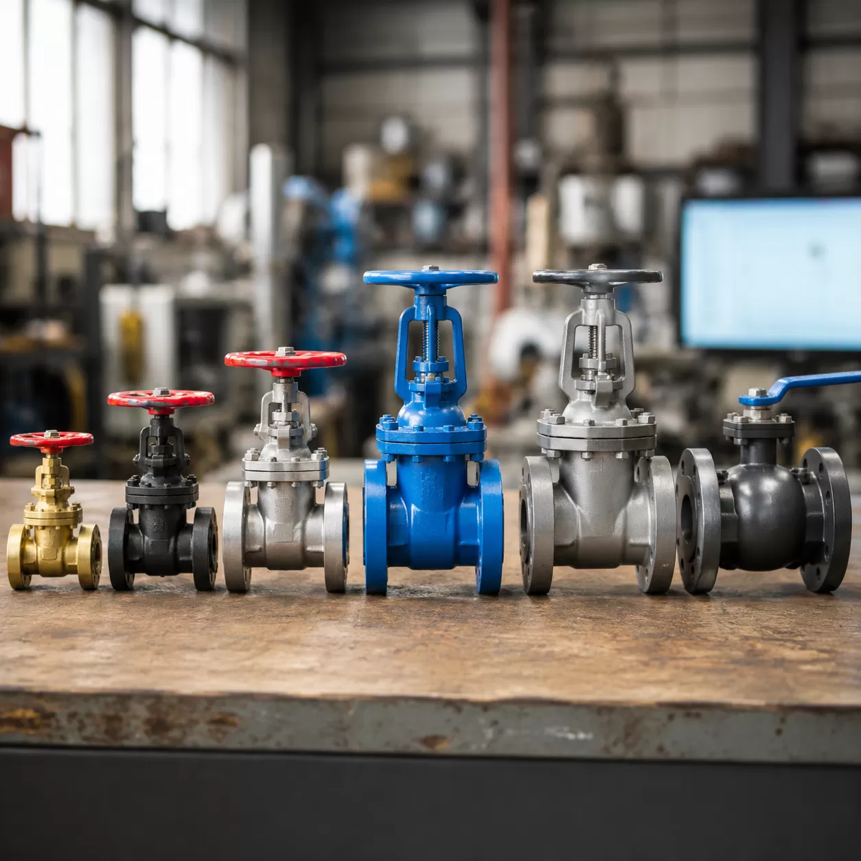
Understanding the specifics of the European Nominal Pressure (PN) system is essential for matching the correct valve to your piping system’s demands. The PN designation indicates the maximum pressure rating in bars at room temperature, approximately 68°F or 20°C. Selecting the right rating prevents premature component failure and ensures long-term operational safety.
PN10 Valves: The Low-Pressure Utility Standard
A PN10 valve is rated for a maximum allowable working pressure (MAWP) of 10 bar (145 psi). These valves are engineered for low-pressure applications where system stresses are minimal.
- Common Applications: Water distribution networks, low-pressure irrigation systems, HVAC cooling loops, and gravity-fed drainage lines.
- Material Selection: Frequently constructed with a ductile iron valve body or cast iron to keep project costs economical without sacrificing basic structural integrity.
PN16 Valves: The Global Industrial Workhorse
The PN16 valve represents the most widely specified metric pressure class across commercial and industrial sectors. Rated for 16 bar (232 psi) at ambient temperatures, this class offers an ideal balance of pressure capacity, material weight, and cost efficiency.
- Common Applications: Industrial process piping, municipal water treatment facilities, chemical processing lines, and fire protection systems.
- Why It Rules the Market: It serves as the baseline standard for most standard industrial pump and piping layouts worldwide. If you are dealing with general fluid handling, our rugged industrial valves are built to handle daily operational cycling in demanding pipeline systems.
PN25 Valves: The High-Pressure Upgrade
When a system exceeds standard utility thresholds, a PN25 valve is required. Rated for 25 bar (362 psi), these heavy-duty components provide the necessary safety margin for high-stress environments.
- Common Applications: High-rise building booster pump stations, long-distance water transmission pipelines, and medium-pressure steam processing.
- Material Selection: These valves regularly step up from iron to cast steel, such as carbon steel WCB, or stainless steel to manage the elevated mechanical stresses safely.
Deep-Dive Profile: Class 150 Valves
The North American Benchmark
In the United States and across North American industrial process piping networks, the Class 150 valve stands as the definitive benchmark for pressure design. Governed by the ASME B16.34 valve standard, this classification does not represent a static pressure limit of 150 psi. Instead, a Class 150 rating designates a specific pressure-temperature class. It ensures that the valve body, whether constructed as a ductile iron valve body or a carbon steel WCB pressure rating standard, provides a predictable piping system safety margin under shifting operational demands.
The Pressure-Temperature Relationship
The primary characteristic of a Class 150 valve is its dynamic maximum allowable working pressure (MAWP). As system temperatures rise, the material strength of the valve decreases, requiring a controlled drop in allowable pressure.
- At Ambient Temperature (-20°F to 100°F): A standard carbon steel Class 150 valve can safely handle up to 285 psi.
- At Elevated Temperatures (e.g., 400°F): The safe working pressure derates significantly, dropping closer to 200 psi.
This fluid relationship means engineers cannot simply look at a nominal pressure bar to psi conversion chart when matching regional specifications. You must verify your exact process temperature against a stainless steel valve rating chart or the corresponding material matrix to ensure the valve remains within safe operating limits.
Ideal Applications
Class 150 valves are uniquely engineered for low-to-medium pressure industrial environments. They are the standard choice for oil and gas distribution, chemical processing, municipal water treatment, and power generation utilities.
When configuring these systems, selecting the proper internal component design is just as critical as the outer shell rating. For example, choosing between a soft seal gate valve vs metal seat gate valve dictates whether your system achieves bubble-tight isolation or survives abrasive, high-temperature slurries. Class 150 valves provide the precise geometry and robust bolt circles required to keep these critical process lines running without failure.
PN16 vs. Class 150 Valve Pressure Rating: Can They Be Safely Interchanged?
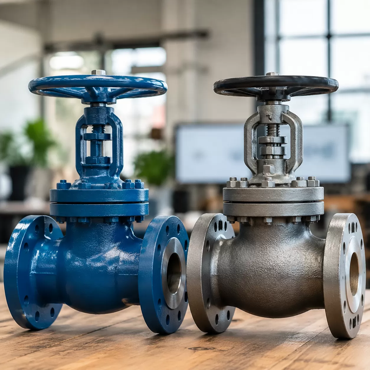
A common question in industrial process piping is whether a PN16 valve and a Class 150 valve can be swapped out for one another. At first glance, they seem to do the same job. However, mixing these standards without checking the specs can compromise your system’s piping system safety margin and lead to catastrophic leaks.
The Pressure Capacity Comparison
The nominal pressure bar to psi conversion shows that these two standards are close, but not identical. A PN16 rating is designed for a maximum allowable working pressure (MAWP) of 16 bar, approximately 232 psi, at ambient temperature. On the other hand, a Class 150 valve is rated for about 19.6 bar, or 285 psi, under similar ambient conditions when using a standard carbon steel WCB pressure rating or ductile iron valve body.
| Valve Pressure Class | Ambient Pressure Rating (Bar) | Ambient Pressure Rating (PSI) |
|---|---|---|
| PN16 Valve | 16.0 bar | ~232 psi |
| Class 150 Valve | 19.6 bar | ~285 psi |
Because a Class 150 valve carries a higher pressure limit at room temperature, substituting a PN16 valve into a true Class 150 system can leave your pipeline under-rated for the maximum potential stress.
The Flange Geometry Barrier
Even if the system pressure is low enough for both ratings, physical installation presents a massive roadblock: flange bolt patterns do not match.
The EN 1092-1 flange standard and the ASME B16.5 standard utilize completely different physical dimensions. This creates a critical flange alignment and mismatch issue because the Bolt Circle Diameter (BCD), the number of bolt holes, and the bolt hole diameters vary between the two styles. If you try to mate a PN16 companion flange to a Class 150 flanged butterfly valve, the bolt holes will not line up.
The Safety Directive
Never force a connection between different standards. Modification shortcuts like slotting bolt holes or skipping bolts destroy the integrity of the joint, leaving the system vulnerable to water hammer surge pressure and joint failure.
- Do not interchange PN16 and Class 150 valves blindly.
- Verify the flange standard of the existing piping before ordering replacement valves.
- Use transition spool pieces or dedicated adapter flanges if you must connect a PN16 system component to a Class 150 line.
The Dangerous Mismatch Trap: DN150 Size Boundary Explained
When setting up industrial process piping, a massive trap lies hidden right at the transition point from smaller piping runs to larger infrastructure. It is a physical reality that catches procurement teams and installers off guard, leading to catastrophic field failures, ruined bolt patterns, and costly project delays.
The Small Diameter Illusion
In smaller sizes—specifically from DN150, or 6 inches, and below—the physical dimensions of a PN16 valve and a Class 150 valve are close enough to trick the untrained eye. Up to the DN150 boundary, the outside diameter of the flanges and the bolt circle diameter (BCD) share a deceptively similar footprint. Installers often develop a false sense of security, assuming that if a valve matches the nominal pipe size, the bolt holes will inevitably line up during installation. This illusion completely shatters once you cross into larger piping dimensions.
The DN200 Breakdown
Once your system scales up to DN200, or 8 inches, and larger, the geometry diverges dramatically.
- Flange Alignment and Mismatch: A DN200 PN16 valve utilizes a 12-hole bolt pattern with a 295 mm BCD.
- The Class 150 Variance: A Class 150 valve in the exact same 8-inch size requires an 8-hole bolt pattern on a 298.5 mm BCD.
Trying to force these two distinct global standards together creates an impossible alignment issue. You cannot slip the bolts through, the sealing surfaces will not compress evenly, and modifying the flange holes in the field completely destroys the structural safety margin of your components. If you are mating these systems near a pumping station, utilizing a dedicated check valve for pump station protection requires absolute verification of these dimensions before ordering.
Procurement Safeguards
Preventing a catastrophic flange alignment failure on the job site requires rigid procurement safeguards. Never order a valve pressure class based purely on nominal size or a hunch.
- Verify the Bolt Circle Diameter (BCD): Demand the exact manufacturing drawings to confirm the hole count and pitch circle diameter match your existing counter-flanges.
- Check Face-to-Face Dimensions: Ensure the end-to-end laying length complies with either EN 1092-1 or ASME B16.34 valve standards depending on your piping layout.
- Enforce Explicit Tagging: Label every line on your blueprint with its precise pressure rating system to eliminate any field confusion between metric and imperial standards.
The Temperature Trap: Understanding Pressure Derating
A valve pressure rating isn’t a static number. If you run a system at elevated temperatures, that maximum allowable working pressure (MAWP) drops significantly. Ignoring this relationship is one of the most common—and dangerous—mistakes in industrial process piping.
Why Metals Weaken Under Heat
As temperatures rise, the microscopic structures of metals expand and become more ductile. This means a ductile iron valve body or a carbon steel WCB pressure rating that handles high pressure at room temperature will lose a massive chunk of its structural strength when things heat up. If your process fluid climbs to 300°F, a valve rated for 232 psi at room temperature might only safely handle 150 psi. Failing to account for this thermal softening leads to seat leakage, body deformation, or catastrophic valve failure.
Visualizing Derating (Comparative Table)
This temperature derating table highlights how temperature dictates the actual working pressure for common materials under the ASME B16.34 valve standard and EN standards.
| Material Class / Standard | Material Type | Pressure Rating at 100°F (38°C) | Pressure Rating at 400°F (204°C) |
|---|---|---|---|
| Class 150 Valve | Carbon Steel (WCB) | 285 psi (19.6 bar) | 200 psi (13.8 bar) |
| Class 150 Valve | Stainless Steel (CF8M) | 275 psi (19.0 bar) | 195 psi (13.4 bar) |
| PN16 Valve | Ductile Iron (GJS-400) | 232 psi (16.0 bar) | 174 psi (12.0 bar) |
| PN25 Valve | Carbon Steel (GP240GH) | 362 psi (25.0 bar) | 319 psi (22.0 bar) |
Note: For exact limits, always cross-reference a comprehensive stainless steel valve rating chart or material data sheet before finalizing your system design.
Surge and Water Hammer Protection
Temperature isn’t the only hidden pressure spike to worry about. High-temperature lines often experience rapid vapor pockets or sudden valve closures that trigger severe water hammer surge pressure. This shockwave sends a kinetic spike through the line that can instantly exceed your piping system safety margin. When designing high-heat systems, it is critical to install heavy-duty industrial valves for water treatment plants and process lines that feature robust, heat-resilient seating to absorb these sudden dynamic pressure shocks without rupturing.
For pumping systems where water hammer is a frequent concern, a micro-resistance slow closing check valve can also help reduce sudden closure impact and protect pumps, pipelines, and downstream equipment.
B2B Selection Guide: Choosing the Right Norite Valve for Your Project
Selecting the correct valve pressure rating for industrial process piping requires a systematic look at your system’s limits. Guessing or over-specifying wastes budget, while under-specifying risks catastrophic component failure. At Norite, we use a streamlined four-step engineering approach to ensure your valve perfectly matches your pipeline requirements.
Step 1: Map Out System Pressure Limits
Identify the maximum allowable working pressure (MAWP) of your pipeline, accounting for normal operating states and potential pressure spikes.
- PN10 and PN16 valves are typically reserved for low-to-medium utility lines.
- PN25 and Class 150 valves handle heavier industrial loads.
- Always ensure your chosen valve pressure class accommodates the system’s test pressure, which is usually 1.5 times the standard operating limit, to maintain a safe piping system safety margin.
Step 2: Establish the Maximum Operating Temperature
Pressure metrics do not exist in a vacuum; they drop as system heat rises. Review your system’s temperature profile alongside the corresponding temperature derating table. For instance, a carbon steel WCB pressure rating changes significantly between 100°F and 600°F. If your process fluids run hot, you must select a higher nominal pressure class than the ambient pressure reading suggests to offset material weakening.
Step 3: Match Regional and Client Compliance Specifications
Navigating international and domestic engineering standards is a necessity for proper integration. You must align your selection with the specific framework dictated by your project blueprint:
- ASME B16.34 Valve Standard: The primary design benchmark for North American projects, regulating dimensions and pressure-temperature ratings.
- EN 1092-1 Flange Standard: The governing European specification detailing explicit metrics for PN-rated systems.
For municipal infrastructure design, reference our comprehensive valve standards guide for EN, AWWA, API, and ISO to guarantee seamless cross-border regulatory approval.
Step 4: Assess Chemical Compatibility & Metallurgy
The fluid inside your pipe dictates the valve body construction. Corrosive chemicals, abrasive slurries, and treated water react differently to metals.
- Ductile Iron Valve Body: Offers excellent tensile strength and shock resistance for standard water, wastewater, and mild industrial lines.
- Carbon Steel and Stainless Steel: Essential for high-temperature, high-pressure, or highly corrosive process media.
Consult a stainless steel valve rating chart to verify that both the chemical resistance and the structural pressure capacity align with your specific media profile before finalizing procurement. If your project involves wastewater, sludge, or high-solids media, a dedicated knife gate valve for sludge and wastewater may be more suitable than a standard gate or butterfly valve.
Frequently Asked Questions (FAQs)
What happens if I use a PN16 valve in a Class 150 system?
Using a PN16 valve in a Class 150 valve system usually results in a mechanical standoff during installation. While their maximum allowable working pressure (MAWP) ratings are relatively similar at ambient temperatures, their flange bolt patterns and bolt circle diameters do not match. For example, if you try to mate a PN16 valve to a Class 150 flange, the bolt holes will not line up, making safe securement impossible. Forcing a fit creates severe pipeline stress and guarantees joint leaks.
Does PN16 mean exactly 16 bar at all operating temperatures?
No, it does not. The “16” in PN16 represents the nominal pressure rating of 16 bar strictly at ambient temperature, usually up to 120°F or 50°C. As the system temperature rises, the structural strength of the ductile iron valve body or carbon steel WCB material degrades. According to the EN 1092-1 flange standard, a PN16 valve operating at 400°F will have a significantly reduced working pressure. Always check a stainless steel valve rating chart or specific material derating curves to ensure your industrial process piping maintains a safe piping system safety margin.
How do I measure the Bolt Circle Diameter (BCD) to prevent a flange mismatch?
To prevent a dangerous flange alignment and mismatch issue, measuring the Bolt Circle Diameter (BCD) accurately is critical.
- For flanges with an even number of holes: Measure from the outside edge of one hole to the inside edge of the directly opposite hole.
- For flanges with an odd number of holes: Measure from the center of one hole to the center of any other hole, then multiply by the appropriate geometric factor based on the hole count, or measure from the center of a hole to the imaginary center axis of the pipe and double it.
Ensuring your BCD matches the specific valve pressure class standard guarantees that your butterfly valve types or gate valves drop perfectly into place during installation.






