
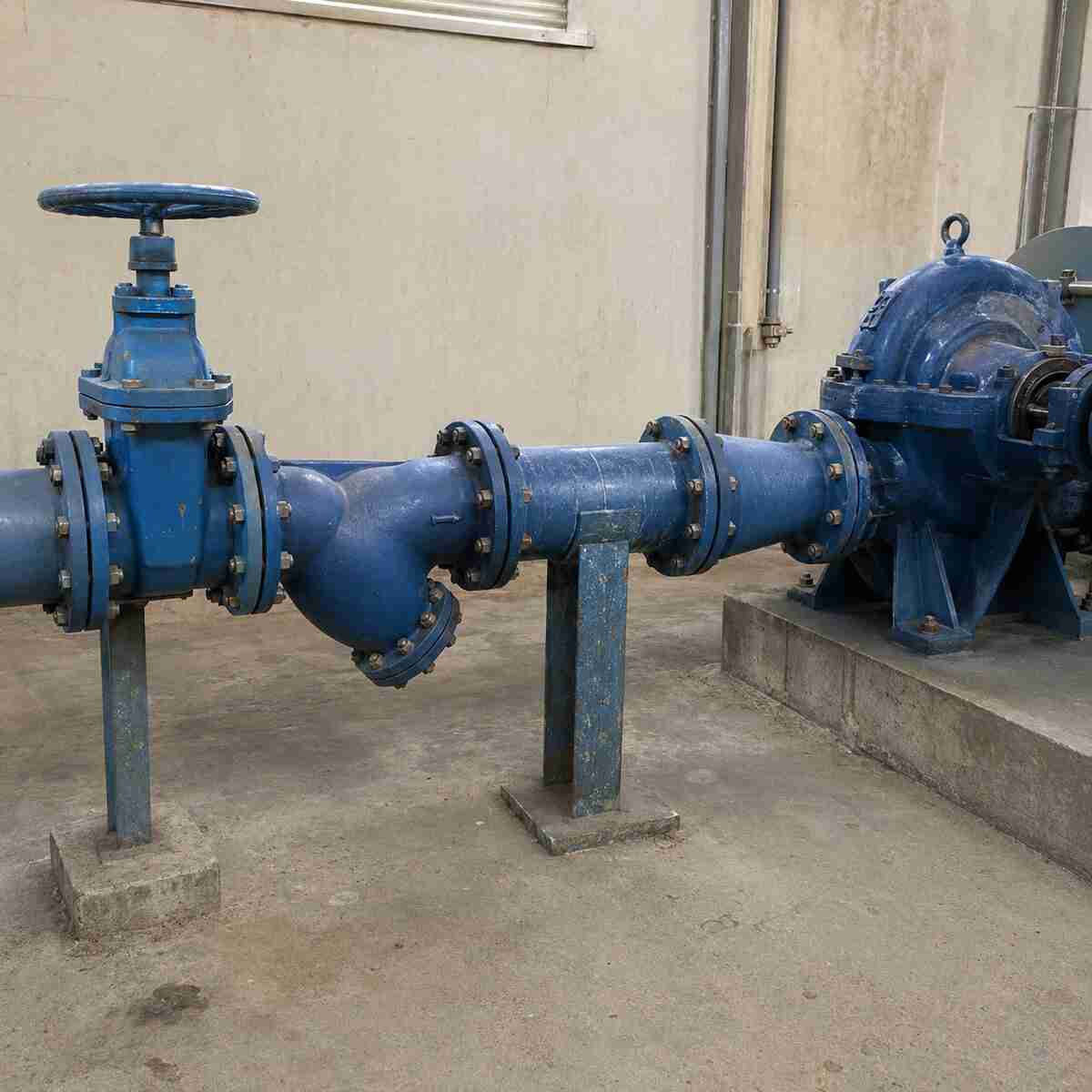
A Y strainer should normally be installed upstream of the component it is intended to protect. This usually means before a pump, control valve, pressure reducing valve, flow meter, heat exchanger, or spray nozzle.
That short answer does not cover every installation.
A strainer on a pump suction line adds resistance, and that resistance increases as the screen collects debris. Placing a Y strainer before an isolation valve may also make the strainer impossible to service without shutting down a larger part of the system. The correct Y strainer installation position must account for equipment protection, pressure loss, pipe layout, isolation, and screen removal.
This guide focuses specifically on where the strainer belongs. For mesh selection, cleaning intervals, and general maintenance, see our complete Y strainer installation guide.
Quick answer: should a Y strainer go before a pump or valve?
Use the following as a starting point:
| Protected component | Normal strainer position | Main reason |
|---|---|---|
| Centrifugal pump | Before the pump, when suction-side filtration is permitted | Stops debris before it reaches the impeller |
| Control valve | Before the control valve | Protects the seat, trim, pilot passages, and actuator-related sensing components |
| Pressure reducing valve | Before the pressure reducing valve | Reduces blockage and unstable pressure control |
| Isolation gate valve | Position depends on maintenance layout | The gate valve may need to isolate the strainer rather than be protected by it |
| Butterfly isolation valve | Position depends on system layout and debris risk | Protection benefit must be balanced against maintenance access |
| Check valve | Before the check valve if debris may obstruct closure | Helps prevent particles from holding the disc open |
| Flow meter | Before the meter, subject to the meter manufacturer’s straight-run requirements | Protects the measuring element without disturbing the required flow profile |
| Heat exchanger or nozzle | Before the equipment inlet | Prevents blockage of small passages |
| Pump discharge valve | Usually upstream of the sensitive valve, but not automatically on the pump discharge | Layout depends on which component requires protection |
The phrase “before the valve” is too broad by itself. A control valve and an isolation valve serve different purposes, so they do not always use the same arrangement.
What determines the correct Y strainer installation position?
The protected component should be identified first. After that, the installer needs to check six practical conditions:
- Which component can be damaged or blocked by debris?
- Can the system tolerate the clean and dirty pressure loss of the strainer?
- Can the strainer be isolated before its cover or drain plug is opened?
- Is there enough clearance to remove the screen?
- Will the selected position disturb flow into a pump, meter, or control device?
- Does the equipment manufacturer permit a strainer in that location?
A correct pipeline strainer installation must answer all six. Installing the strainer immediately before expensive equipment does not help if the screen cannot be removed or if its pressure drop causes pump suction problems.
Should a Y strainer be installed before a pump?

A Y strainer is commonly installed before a pump when rust, stones, welding slag, gasket fragments, or other solid particles could enter the pump.
The strainer should be on the suction side because filtration after the pump cannot protect the impeller from incoming debris. The flow arrow on the strainer body must point toward the pump.
A typical sequence is:
- Water source or suction header
- Upstream isolation valve
- Y strainer
- Required straight suction pipe and reducer arrangement
- Pump suction inlet
The actual spacing between these components must follow the pump manufacturer’s suction-piping instructions. A single universal distance, such as five or ten pipe diameters, should not be applied to every pump. Pump type, suction velocity, elbow position, reducer design, available NPSH, and inlet geometry can change the requirement.
Why pump suction installation needs extra care
Every suction-side fitting creates hydraulic resistance. A clean Y strainer creates some pressure loss. A partially blocked screen creates more.
Excessive suction loss can reduce the pressure available at the pump inlet. Depending on the system, this may contribute to:
- Reduced pump capacity
- Noise or vibration
- Unstable operation
- Cavitation risk
- Loss of prime
- Screen deformation or collapse
- Higher energy use
For that reason, “install the finest possible screen before the pump” is poor selection advice. The screen opening should stop particles large enough to damage the pump while allowing the required flow at an acceptable pressure loss.
The pump supplier should confirm:
- Whether a permanent suction strainer is permitted
- Maximum acceptable clean pressure drop
- Maximum operating differential pressure
- Minimum effective screen area
- Required straight pipe before the suction nozzle
- Acceptable mesh or perforation size
- Whether a temporary commissioning strainer is preferred
When a Y strainer may not be the best pump solution
A standard Y strainer is compact, but its dirt-holding capacity is limited compared with many basket strainers. It may clog quickly in raw water, wastewater, cooling tower water, or lines with heavy construction debris.
Depending on the service, the engineer may specify:
- A basket strainer with a larger screen area
- A duplex strainer for uninterrupted operation
- A suction diffuser designed for the pump arrangement
- A coarse intake screen at the water source
- A temporary startup strainer removed after flushing
- A self-cleaning strainer for a high debris load
Do not assume that every pump needs a permanent Y strainer. Some pump manufacturers discourage restrictive devices near the suction nozzle. The pump data sheet and project specification should decide the final arrangement.
Should the Y strainer be directly connected to the pump?
Direct connection is not automatically correct.
A strainer installed too close to a pump inlet can affect the inlet flow profile, especially when it is combined with an elbow, reducer, or partially open valve. The pump may require a straight section of pipe between the strainer and suction nozzle.
The suction pipe should also be independently supported. The Y strainer must not carry the weight of the pipe or force the pump nozzle into alignment. Large flanged strainers need their own support or a support arrangement shown on the piping drawing.
Confirm the following before approving a direct connection:
- Pump manufacturer’s minimum straight-run requirement
- Reducer orientation
- Pipe support locations
- Screen-removal clearance
- Drain access
- Flange compatibility
- Expected pressure loss at design flow
If these points cannot be satisfied, move the strainer farther upstream or use a different filtration arrangement.
Should a Y strainer be installed before a valve?
A Y strainer should normally be installed before a control valve, pressure reducing valve, or other valve with small internal passages.
Debris can score a control valve seat, block a pilot line, restrict an orifice, or prevent the valve from closing correctly. Upstream filtration lowers that risk.
A practical control-valve station often includes:
- Upstream isolation valve
- Y strainer
- Pressure gauge or gauge connection
- Control valve or pressure reducing valve
- Downstream pressure gauge
- Downstream isolation valve
The exact order can change with the control-valve design. Pilot-operated valves may have separate pilot strainers, sensing lines, or manufacturer-specified upstream pipe lengths.
For a pressure reducing station, refer to the valve manufacturer’s installation drawing rather than relying only on a generic pipeline arrangement.
Y strainer before an isolation valve: is it necessary?
An isolation gate valve or butterfly valve does not always need a Y strainer immediately before it.
Isolation valves are usually included so operators can shut off a pipeline section or isolate equipment for maintenance. If the strainer is placed upstream of the only isolation valve, operators may have no safe way to depressurize and open the strainer.
A more serviceable arrangement is usually:
- Upstream isolation valve
- Y strainer
- Protected equipment or control valve
- Downstream isolation valve
This layout allows the strainer and protected component to be isolated from both sides. The trapped section must still be depressurized and drained before maintenance.
If the line contains heavy debris that could damage an isolation valve seat or stop a butterfly disc from closing, upstream filtration may still be useful. In that case, provide another means of isolating the strainer.
The correct question is not simply whether the strainer goes before or after the isolation valve. The question is whether the strainer can protect the required equipment and still be isolated safely.
Should a Y strainer be installed before a pressure reducing valve?
Yes, in most water systems the Y strainer is installed upstream of the pressure reducing valve.
Pressure reducing valves can contain narrow pilot passages, seats, diaphragms, sensing lines, and restriction orifices. Rust, sand, and pipe scale can cause unstable downstream pressure or prevent tight closure.
A common arrangement includes:
- Upstream isolation valve
- Y strainer
- Upstream pressure gauge
- Pressure reducing valve
- Downstream pressure gauge
- Downstream isolation valve
Some stations also require a bypass, relief valve, or parallel pressure reducing line. These features depend on the pressure-control design and should not be added without reviewing the project requirements.
The screen must not be selected by habit. Use the pressure reducing valve manufacturer’s recommended filtration opening and verify the pressure loss at the required flow.
Should a Y strainer be installed before a check valve?
A check valve can fail to close if a piece of debris becomes trapped between the disc and seat. A strainer installed upstream can reduce this risk.
The need for a separate Y strainer depends on:
- Expected debris size and quantity
- Check valve design
- Required flow rate
- Allowable system pressure loss
- Whether other upstream filtration already exists
- Maintenance access
On a pump discharge line, the check valve is normally installed after the pump to stop reverse flow when the pump stops. A suction-side strainer can protect both the pump and the downstream check valve from incoming debris.
Adding another Y strainer on the discharge side only to protect the check valve may create unnecessary pressure loss. Use one only when the water quality and valve design justify it.
For pump discharge check-valve selection, see our guide to the H44X swing check valve.
Where should a Y strainer be placed around a pump isolation valve?
For a pump suction line that requires filtration, the normal functional order is:
| Position | Component | Purpose |
|---|---|---|
| 1 | Suction source or header | Supplies the pump |
| 2 | Full-bore isolation valve | Isolates the branch for maintenance |
| 3 | Y strainer | Removes damaging solids |
| 4 | Straight pipe and reducer arrangement | Provides suitable flow into the pump |
| 5 | Pump | Moves the liquid |
The isolation valve should remain fully open during pump operation. A throttled suction valve increases inlet loss and can disturb the flow entering the pump.
Gate valves are commonly used for suction isolation because they provide a relatively unobstructed flow path when fully open. The final valve type must match the pressure class, pipe size, media, and project specification.
The installation also needs a safe way to release trapped pressure between closed valves. Never loosen a Y strainer cover while the chamber is pressurized.
Correct Y type strainer direction
The arrow cast or marked on the body determines the Y type strainer direction. It must point in the same direction as pipeline flow.
Do not use the cover position, flange shape, or Y branch angle to guess which end is the inlet. Two strainers that look similar may have different internal screen support arrangements.
Installing the unit backward can:
- Load the screen from the wrong side
- Increase pressure loss
- Allow debris to collect incorrectly
- Damage or collapse the screen
- Make blowdown less effective
- Release collected debris downstream
Check the arrow before tightening the flange bolts. After installation, verify it again against the piping and instrumentation diagram and the actual operating flow.
Which way should the Y branch face?
The Y branch contains the screen, cover, and usually the drain or blowdown connection. Its orientation affects debris collection and maintenance.
Liquid pipelines
On a horizontal liquid pipeline, the Y branch normally points downward. Gravity keeps collected solids in the lower chamber and reduces the chance that debris will return to the main flow.
The branch does not have to point at an exact clock position unless the manufacturer specifies one, but the drain should remain low and the screen must be removable.
Do not point the Y branch upward in normal liquid service. Debris can fall back into the pipeline when flow stops, and air may collect in the chamber.
Steam and gas pipelines
Steam and gas installations may require the screen chamber to face horizontally rather than straight down. This arrangement can reduce unwanted condensate collection in the strainer body.
Steam service also needs correct drainage, warm-up, blowdown, and condensate management. Follow the strainer manufacturer’s installation manual and the steam-system design rather than applying a liquid-water layout.
Vertical pipelines
Many Y strainers can be installed in a vertical pipe only when flow moves downward and the Y branch can point downward.
Bottom-to-top flow is generally unsuitable because collected material may fall back into the upstream pipe when flow stops. Some manufacturers permit additional orientations for specific models, so the product drawing remains the controlling document.
The NORITE GL41H Y-Type Filter can be supplied for horizontal or suitable vertical pipeline arrangements. Confirm flow direction, available clearance, and operating media when requesting a quotation.
Installation position before a flow meter
A Y strainer may protect a flow meter from rust, scale, and other debris, but it can also disturb the flow profile.
Installers must check the meter manufacturer’s requirements for:
- Upstream straight pipe
- Downstream straight pipe
- Acceptable valves and fittings near the meter
- Flow conditioner requirements
- Strainer position
- Maximum allowable pressure loss
The strainer should not automatically be connected directly to the meter inlet. If the meter requires an undisturbed upstream run, place the strainer before that straight section.
The same rule applies to control valves and instruments that depend on a stable flow profile.
Installation position before a heat exchanger or nozzle
A Y strainer is normally installed upstream of heat exchangers, cooling coils, spray nozzles, irrigation emitters, and other equipment with narrow flow passages.
The filtration opening should be smaller than the minimum passage that requires protection, but it must still pass the system flow without excessive pressure loss.
If blockage would stop an essential process, consider a duplex or parallel strainer arrangement. A single isolated bypass can keep the system running, but opening an unfiltered bypass may expose the protected equipment to the debris the strainer was installed to remove.
How much space should be left around the strainer?

There is no universal maintenance clearance for every Y strainer.
The required space depends on:
- Screen length
- Cover design
- Drain or blowdown connection
- Strainer size and weight
- Bolt-removal direction
- Lifting access
- Insulation thickness
- Nearby walls, floors, valves, and pipe supports
Use the manufacturer’s dimensional drawing to verify screen withdrawal clearance. The cover may open successfully while the screen remains trapped against a wall or structural beam.
For large strainers, allow room for lifting equipment. Do not plan to support a heavy screen or cover by hand during removal.
Pressure gauges and differential pressure monitoring
A pressure gauge upstream and another downstream can help operators identify screen blockage. A differential pressure gauge or transmitter provides a more direct indication.
The acceptable differential pressure must come from the strainer manufacturer’s data and the system design. Do not use one cleaning threshold for every screen material and size.
As debris accumulates:
- Differential pressure rises.
- Available flow may fall.
- Pump suction pressure may decrease.
- The screen experiences greater mechanical load.
- An unsupported or overloaded screen may deform or fail.
Clean the strainer before the differential pressure reaches the manufacturer’s allowable limit.
Common pipeline strainer installation mistakes
Installing it after the equipment that needs protection
A discharge-side strainer cannot protect a pump impeller from debris entering through the suction pipe.
Treating every valve the same
Control valves normally need upstream filtration. An isolation valve may need to be upstream of the strainer so maintenance staff can isolate it.
Ignoring pump suction pressure
A fine or clogged screen can reduce available inlet pressure. Pump suction conditions must be checked at the maximum expected strainer differential pressure.
Placing the Y branch upward
This position can allow debris to return to the main pipe and may prevent effective drainage.
Installing against the flow arrow
The internal screen is designed for a specific flow direction. Reversing the body can damage the screen and reduce filtration performance.
Leaving no room for screen removal
Visible access to the cover is not enough. The complete screen must be able to slide out.
Using the strainer to correct pipe misalignment
Pulling flanges into position with the bolts transfers pipe stress into the strainer body. Align and support the pipeline before installation.
Omitting isolation and depressurization provisions
A screen cannot be cleaned safely while the body contains pressure, hot liquid, steam, gas, or hazardous media.
Specifying mesh without pressure-loss data
A finer screen traps smaller particles but normally clogs faster and creates more resistance. Select the opening according to the protected equipment and operating conditions.
Y strainer installation position checklist
Before approving the pipeline layout, confirm:
- The protected component has been identified.
- The body arrow matches actual flow direction.
- The Y branch orientation suits the media.
- Vertical installation, if used, is approved for the selected model.
- The pump supplier accepts the suction-side strainer.
- Clean and dirty pressure losses have been reviewed.
- Pump NPSH conditions remain acceptable.
- Required straight pipe lengths are maintained.
- Isolation valves allow safe maintenance.
- Trapped pressure can be released safely.
- The drain or blowdown connection is accessible.
- The screen can be removed without cutting the pipe.
- The strainer and adjacent pipe have adequate support.
- Screen opening and material match the service.
- Flanges, gaskets, pressure rating, and temperature rating are compatible.
- Differential pressure can be monitored where required.
- Startup and post-flushing inspection are included in the commissioning plan.
Information to include in a Y strainer RFQ
To confirm the correct installation position and select a suitable strainer, provide:
- Pipeline size and connection standard
- Design pressure and operating pressure
- Design temperature and operating temperature
- Flow rate
- Fluid type
- Expected debris type and particle size
- Required mesh or perforation opening
- Maximum acceptable pressure loss
- Horizontal or vertical pipe orientation
- Actual flow direction
- Protected pump, valve, meter, or equipment
- Pump suction conditions, if applicable
- Available screen-removal clearance
- Body and screen material requirements
- Coating or drinking-water approval requirements
- Drain, blowdown, and gauge connection requirements
- Quantity and project destination
A marked piping drawing or P&ID is more useful than a request that only lists DN size and pressure class.
FAQs about Y strainer installation position
Does a Y strainer go before or after a pump?
When a pump requires protection from incoming solids and the pump manufacturer permits suction-side filtration, the Y strainer goes before the pump. A strainer installed after the pump cannot protect the impeller from incoming debris.
Can a Y strainer damage a pump?
A correctly sized and maintained strainer protects the pump. An undersized, excessively fine, or clogged suction strainer can reduce inlet pressure and contribute to cavitation or unstable operation.
Does a Y strainer go before or after an isolation valve?
An upstream isolation valve is normally needed so the strainer can be shut off for cleaning. A second downstream isolation valve may be required to isolate the complete maintenance section.
Does a Y strainer go before a control valve?
Yes. It is normally installed upstream to stop debris from reaching the control-valve seat, trim, pilot passages, or sensing components.
Should a Y strainer be installed before a pressure reducing valve?
Yes, unless the pressure reducing valve manufacturer specifies another arrangement. The manufacturer should also confirm the required screen opening.
Can a Y strainer be installed vertically?
Some models can be installed in a vertical pipe with downward flow and the Y branch pointing downward. Avoid bottom-to-top installation unless the manufacturer explicitly approves it.
Which direction should the Y branch face?
For horizontal liquid service, it normally faces downward. Steam and gas applications may require a horizontal screen chamber. Always check the product installation manual.
How close can a Y strainer be to a pump?
There is no universal distance for every pump. Follow the pump manufacturer’s requirements for straight suction pipe, reducers, elbows, valves, and other fittings.
Is a bypass required around a Y strainer?
A bypass may be useful when shutdown is unacceptable, but an open bypass sends unfiltered media to the protected equipment. Continuous processes may be better served by a duplex or parallel strainer arrangement.
Is a Y strainer suitable for wastewater?
It may be suitable for water containing limited coarse debris, but a standard Y strainer can clog quickly in wastewater with fibers, rags, or heavy solids. Screen type, open area, cleaning method, and alternative filtration equipment must be evaluated.
Final installation recommendation
The correct Y strainer installation position is upstream of the component that requires protection, but the surrounding layout changes according to the equipment.
Install it before a pump only after checking suction pressure, NPSH, screen area, pressure loss, and the pump manufacturer’s piping requirements. Install it before a control valve or pressure reducing valve to protect internal passages and seating surfaces. For isolation valves, arrange the valves so operators can isolate, drain, and open the strainer safely.
Follow the body arrow for flow direction. Keep the Y branch downward for most horizontal liquid lines, and use downward flow for vertical installations unless the selected model allows another arrangement.
NORITE supplies GL41H Y-Type Filters for municipal water, industrial water, HVAC, pump stations, and equipment-protection pipelines. Send us your P&ID, flow rate, working pressure, media, screen requirement, and available installation space through the NORITE contact page to confirm the appropriate size and installation arrangement.






