
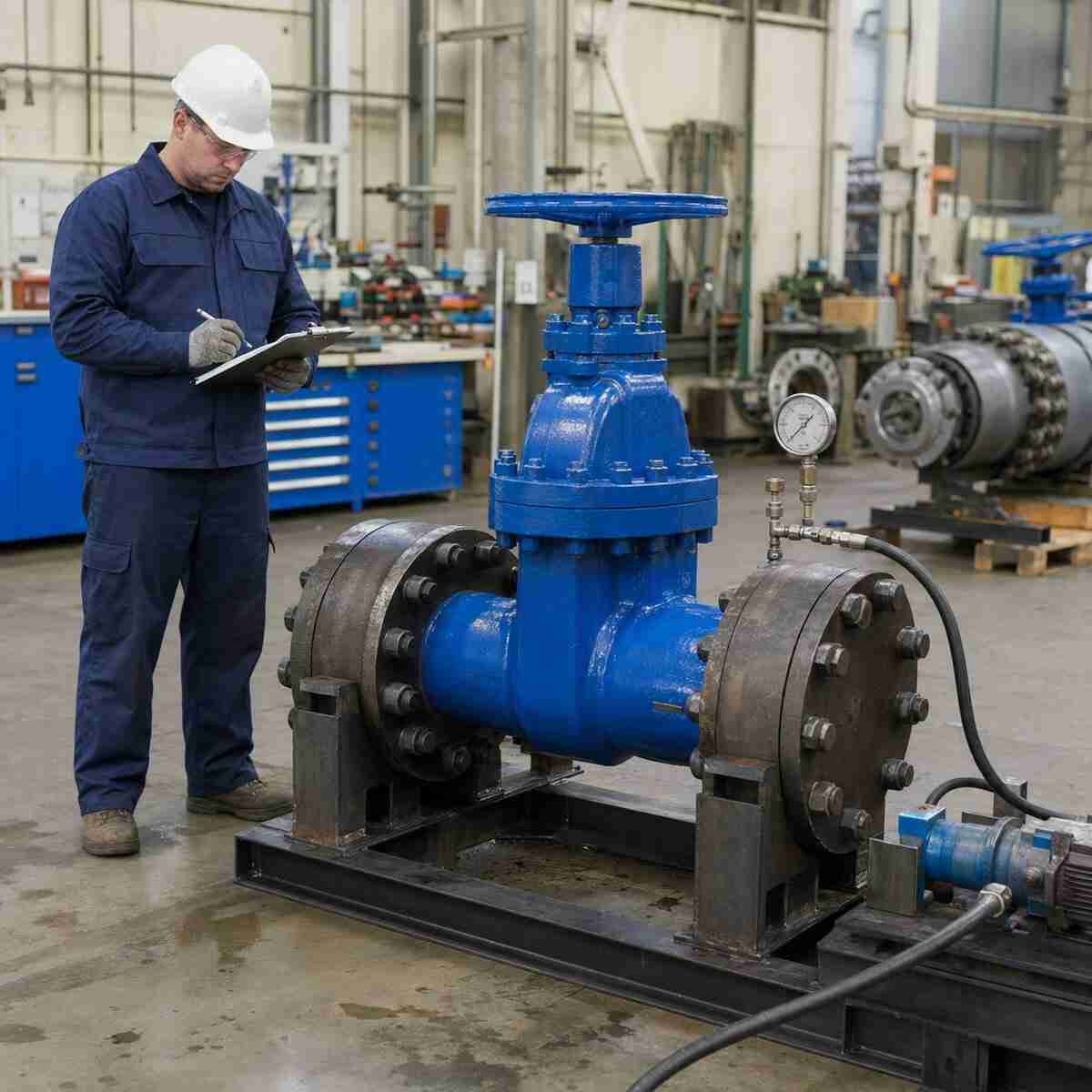
A valve test certificate that only says “hydrostatic test: passed” does not tell a buyer enough. Was the valve body tested, the seats tested, or both? What pressure was applied? In which direction? For how long? Was leakage actually measured, and which acceptance standard was used?
These questions matter because a valve can pass a shell test and still leak through the seat. It can also pass a low-pressure air test but fail a high-pressure liquid test—or the reverse—depending on its design, seat material and condition.
This guide explains valve hydrostatic testing, shell testing, seat leakage testing, backseat testing, API 598 valve testing and ISO 5208 valve test requirements from a buyer’s perspective. It also shows what to check on a valve test certificate before approving a shipment.
Quick Answer
- A shell test checks the strength and external tightness of the pressure-containing body, bonnet, cover and fixed joints. The valve is normally partially open, and no visually detectable leakage through the pressure boundary is accepted.
- A seat test, also called a closure or seat leakage test, checks leakage past the closed gate, disc, plug or ball. Its acceptance limit depends on the test standard, valve type, seat material, size and test medium.
- API 598 gives required and optional factory tests, test pressures, minimum holding times and leakage limits for common isolation valves.
- ISO 5208 provides pressure-testing practices for metallic industrial valves and a series of closure leakage rates from Rate A, the tightest, through progressively higher permitted rates.
- “Tested to API 598” or “tested to ISO 5208” is incomplete unless the purchase order also identifies the applicable edition, required tests, leakage acceptance, test direction and documentation.
Shell Test vs Seat Test vs Backseat Test
| Test | What it verifies | Typical valve position | Common test medium | Main acceptance question |
|---|---|---|---|---|
| Shell test | Strength and tightness of the body, bonnet, cover, fixed joints and pressure-retaining structure | Partially open | Usually clean water or another permitted liquid | Is there any visible external leakage or structural damage? |
| High-pressure seat test | Closure tightness at a specified high differential pressure | Fully closed | Water or another permitted liquid; gas may be specified under controlled conditions | Is measured seat leakage within the applicable limit? |
| Low-pressure seat test | Sensitivity of the closed seat to leakage at low pressure | Fully closed | Air, nitrogen or another suitable inert gas | Are bubbles or measured gas leakage within the limit? |
| Backseat test | Tightness between the stem or shaft and the bonnet backseat feature | Fully open | High- or low-pressure medium, as specified | Is there leakage past the backseat? |
The shell and seat tests are complementary, not interchangeable. The shell test checks external leakage through the pressure boundary. The seat test checks internal leakage through the closure mechanism.
What Does “Hydrostatic Testing” Actually Mean?
Hydrostatic testing means that a liquid—normally water—is used as the pressure medium. It does not, by itself, identify which part of the valve is being tested.
A manufacturer may perform:
- A hydrostatic shell test on the pressure-containing structure
- A hydrostatic high-pressure closure test on the seats
- A pneumatic low-pressure closure test using air or nitrogen
Therefore, the phrase “valve hydrostatic testing” should not be treated as a complete test specification. A proper purchase order should separately define the shell test, high-pressure closure test, low-pressure closure test, backseat test when applicable, and any special test.
Before setting test pressure, confirm the valve’s actual rating. The relationship between PN10, PN16, PN25 and ASME Class ratings is explained in our valve pressure rating guide.
Why Valve Pressure Testing Matters
Production pressure testing can reveal problems that visual inspection alone cannot find, including:
- Casting porosity, cracks or defective repairs
- Leakage at body-to-bonnet or body-to-cover joints
- Damaged gaskets, O-rings or fixed stem seals
- Scratched, contaminated or incorrectly machined seats
- Misalignment between the stem, disc, wedge, plug or ball
- Incorrect assembly or closing torque
- Leakage behind a seat ring rather than across the main sealing interface
- A one-way valve incorrectly represented as bidirectional
For buyers, testing also confirms whether the delivered valve matches the agreed design basis. The test standard must be considered together with the valve type, pressure rating, seat material and product standard. Our API valve guide provides a separate comparison of API gate, ball, check and globe valve functions and applicable project considerations.
API 598 Valve Testing: What Buyers Should Know
API 598, Valve Inspection and Testing, is widely specified for factory inspection and pressure testing of resilient-seated, nonmetallic-seated and metal-to-metal-seated gate, globe, plug, ball, check and butterfly valves.
At the time of writing, the current publication is API 598, 11th Edition, February 2023. It covers:
- Visual examination of cast pressure-containing and closure components
- Shell testing
- Backseat testing where the valve has an applicable backseat feature
- Low-pressure closure testing
- High-pressure closure testing
- Double-block-and-bleed closure testing when specified
- Optional high-pressure pneumatic shell testing
- Certification and retesting requirements
Not every closure test is automatically required for every valve type, size and pressure class. API 598 identifies required and optional tests in a test matrix. The purchase order should state any optional test the buyer requires.
API 598 is a test standard, not a complete valve design specification. It is normally used together with standards such as API 594, API 600, API 602, API 608, API 609 or API 623, depending on the product. For a wider comparison, see our EN, AWWA, API and ISO valve standards guide.
ISO 5208 Valve Test: What Is Different?
ISO 5208:2015, Industrial valves—Pressure testing of metallic valves, establishes basic examinations and tests for:
- Integrity of the valve pressure boundary
- Closure tightness
- Structural adequacy of the closure mechanism
ISO 5208:2015 remains current and was reviewed and confirmed in 2025. It is intended to be applied with the applicable valve product standard. If the product standard contains different requirements, the product standard takes precedence.
One important feature of ISO 5208 is its graded closure leakage system. The named rates are:
Rate A, Rate AA, Rate B, Rate C, Rate CC, Rate D, Rate E, Rate EE, Rate F and Rate G.
Rate A is the tightest and requires no visually detectable leakage for the specified test duration. The other rates permit quantified leakage that varies with nominal valve size and whether the test medium is liquid or gas.
The purchase order should state the required ISO 5208 leakage rate. Writing only “seat test according to ISO 5208” can leave the acceptance criterion unclear.
API 598 vs ISO 5208
| Item | API 598 | ISO 5208 |
|---|---|---|
| Current basis used in this guide | 11th Edition, 2023 | ISO 5208:2015, confirmed in 2025 |
| Primary use | Inspection and production pressure testing of specified valve families | General pressure testing of metallic industrial valves |
| Pressure designation context | Closely connected with ASME Class and referenced API product standards | Supports PN- and Class-designated valves with the applicable product standard |
| Closure acceptance | Tables based on valve type, seat type, size and test medium | Graded leakage rates A through G, including intermediate AA, CC and EE rates |
| Required vs optional tests | Matrix varies by valve type, size and class | Matrix varies by valve type, size and PN or Class |
| Buyer’s key action | Specify optional tests, edition, witness requirements and documentation | Specify the leakage rate, product standard, test options and documentation |
The standards should not be converted casually. “API 598 equals ISO 5208 Rate A” is not a reliable universal statement for all valves. A project specification should name one clear acceptance basis or provide an approved cross-reference for the exact valve design.
How a Valve Hydrostatic Shell Test Is Performed
The following sequence describes a typical factory shell test. The approved procedure and applicable standard always control.
1. Confirm the Test Basis
The technician should verify:
- Valve type and model
- DN or NPS size
- PN or ASME Class rating
- Body, bonnet and cover materials
- Applicable product and test standards, including editions
- Required test pressure and minimum holding time
- Purchaser-approved test procedure
- Witness, hold or review points in the Inspection and Test Plan
A universal “1.5 times nameplate pressure” rule should not replace this review. API 598, ISO 5208, EN, AWWA and product-specific standards can calculate or tabulate pressure differently.
2. Inspect the Valve Before Testing
Confirm valve identification, casting condition, assembly, dimensions and cleanliness before applying pressure. External paint or another coating capable of masking shell leakage should not be applied before the original shell inspection unless the applicable standard permits it.
3. Install the Valve on the Test Bench
Seal the valve ends using suitable blind flanges, plates or fixtures. The fixture must not impose loads or clamping forces that artificially improve seat or body-joint sealing. This is particularly important for wafer butterfly and wafer check valves.
4. Fill and Vent the Valve
Fill the body cavity with the permitted liquid and remove trapped air. Trapped air makes the system more hazardous because compressed gas stores much more energy than an incompressible liquid. It can also make the pressure unstable and complicate leak diagnosis.
5. Place the Valve in the Correct Position
For the API 598 shell procedure, the assembled valve is generally partially open so that the pressure reaches the relevant body cavity and pressure-containing structure. Packing glands and stem-seal arrangements are prepared as required by the approved procedure.
6. Increase and Hold the Test Pressure
Raise pressure gradually to the specified value. Begin the official holding period only after the valve is fully prepared, full test pressure has been reached and readings are stable.
7. Inspect All Pressure-Boundary Areas
Check the body, bonnet, cover, fixed joints, plugs and relevant stem-seal areas. Under API 598, visually detectable leakage through the shell pressure boundary or a fixed body joint is not permitted. Acceptance of adjustable packing behavior is more specific, so it should not be confused with acceptance of leakage through a nonadjustable O-ring or fixed seal.
8. Depressurize, Drain and Protect the Valve
Release pressure in a controlled manner. Drain and dry the valve, especially for carbon steel, stainless steel, oxygen service, low-temperature service or long sea transport. Reapply approved rust preventive, flange protectors and packaging after final inspection.
Typical API 598 Test Pressures
The correct pressure must come from the applicable edition, valve product standard, pressure-temperature rating and purchase specification. The following overview is useful for understanding the logic, but it is not a substitute for the standard tables.
Shell Test Pressure
For many steel and nonferrous alloy valves, API 598 links the minimum hydrostatic shell pressure to 1.5 times the valve pressure rating at 38°C (100°F), with prescribed rounding. API 598 also gives specific tabulated values for ductile-iron and gray-iron valves.
Examples from API 598 include:
- Ductile-iron Class 150 shell test: minimum 26 bar gauge (400 psig)
- Ductile-iron Class 300 shell test: minimum 66 bar gauge (975 psig)
These examples must not be applied automatically to PN-rated water valves or different materials.
High-Pressure Closure and Backseat Pressure
For many valves other than butterfly and check valves, API 598 sets high-pressure closure and backseat pressure at 110% of the maximum allowable pressure at 38°C (100°F) under the applicable purchase specification.
For butterfly valves, high-pressure closure is connected to 110% of the design differential pressure at 38°C. This distinction is important because the maximum seat differential can be lower than the body pressure rating.
Low-Pressure Closure and Backseat Pressure
API 598 specifies 5.5 ± 1.5 bar gauge (80 ± 20 psig) for the applicable low-pressure closure and backseat tests.
Minimum API 598 Test Durations
The minimum holding time increases with valve size. The following buyer-friendly summary reflects the API 598 duration structure:
| Valve size | Shell test | Backseat test | Check-valve closure | Other-valve closure |
|---|---|---|---|---|
| DN ≤ 50 / NPS ≤ 2 | 15 s | 15 s | 60 s | 15 s |
| DN 65–150 / NPS 2½–6 | 60 s | 60 s | 60 s | 60 s |
| DN 200–300 / NPS 8–12 | 120 s | 60 s | 120 s | 120 s |
| DN 350–600 / NPS 14–24 | 300 s | 60 s | 120 s | 120 s |
| DN > 600 / NPS > 24 | 600 s | 120 s | 240 s | 240 s |
The closure duration applies to each required seat sealing direction. Time spent filling the valve, increasing pressure or waiting for unstable readings does not replace the specified inspection period at full pressure.
How a Valve Seat Leakage Test Is Performed
A seat leakage test is performed with the closure member in the closed position. Pressure is applied to the specified side, while leakage is observed or measured on the opposite side or through a cavity connection.
High-Pressure Liquid Seat Test
The high-pressure test evaluates the closure mechanism at the specified liquid pressure. Leakage may be measured as drops per minute or volume per unit time, depending on the valve and acceptance standard.
The test should confirm that leakage is actually coming through the seat interface. Leakage behind the seat ring, through the disc, past a shaft seal or through another unintended path is not the same as permitted seat-interface leakage.
Low-Pressure Gas Seat Test
The low-pressure test uses air, nitrogen or another permitted inert gas. Leakage is normally detected through bubbles, a calibrated volumetric device or another validated measurement method.
Gas can reveal small leak paths that are less obvious during a liquid test. However, pneumatic testing involves greater stored energy and requires suitable safety controls.

Resilient Seats vs Metal Seats
Under API 598, resilient-seated valves are subject to no leakage for the specified test duration. Metal-seated valves can have a limited, size-dependent leakage allowance. Check valves have separate limits because their seating behavior differs from that of manually or actuated isolation valves.
Under ISO 5208, the specified leakage rate determines acceptance. Buyers who require bubble-tight shutoff should state the exact rate and test medium rather than relying on the phrase “zero leakage.”
A resilient seated gate valve and a metal-seated gate valve may share the same nominal size and body pressure rating but should not be assumed to have the same closure leakage acceptance.
Test Direction Depends on Valve Design
Applying pressure from the wrong side can produce a misleading pass or unfair failure. API 598 includes direction-specific procedures.
| Valve design | Typical closure-test direction consideration |
|---|---|
| Bidirectional gate valve | Apply pressure successively to each side of the closed valve, with the opposite side available for leakage observation |
| Globe valve | Apply pressure in the specified direction, generally under the disc for the API 598 procedure |
| Check valve | Apply test pressure from the downstream side to verify reverse-flow sealing |
| Unidirectional valve | Apply pressure only from the marked pressure side and use the rated differential for that direction |
| Butterfly valve | Direction requirements depend on the API 609 category, resilient-seat construction and preferred-flow rating |
| Floating or downstream-seated ball valve | The procedure must fully pressurize the necessary body cavity so that gradual cavity filling cannot hide leakage |
| Double-block-and-bleed valve | Test seat leakage into the body cavity using the agreed successive or simultaneous DBB method |
For example, test requirements for a double eccentric butterfly valve should consider its seat design and permitted differential in each direction. A swing check valve must be evaluated as a non-return valve rather than tested like a manually closed gate valve.
Backseat Testing Is Not a Permission to Repack a Live Valve
The backseat is a feature on some rising-stem gate and globe valves that limits leakage between the stem and bonnet when the valve is fully open. Under API 598, the backseat test applies to valves with this feature, except bellows-seal valves.
A successful backseat test confirms the feature’s test performance. It should not be interpreted as permission to adjust or replace packing while an installed valve is pressurized. Site maintenance must follow the manufacturer’s instructions, plant isolation procedures and applicable safety rules.
API 598 Seat Leakage vs ISO 5208 Leakage Rates
API 598
API 598 separates closure leakage acceptance by:
- Resilient-seated or metal-seated construction
- Check or non-check valve
- Valve size
- Liquid or gas test medium
For resilient-seated valves, the allowable result is no leakage during the required duration. For metal-seated non-check valves, liquid and gas limits increase with NPS. Metal-seated check valves use separate volumetric limits.
ISO 5208
ISO 5208 uses graded leakage rates. Rate A is no visually detectable leakage; the remaining rates permit calculated liquid or gas leakage proportional to DN. The correct rate should come from the product standard, valve specification or agreement between purchaser and manufacturer.
Why “Zero Leakage” Must Be Defined
“Zero leakage” can mean different things in commercial documents:
- No visible drops during a liquid test
- No observed bubbles during a defined gas test period
- Leakage below the sensitivity of the measurement system
- ISO 5208 Rate A
- A separate project-defined criterion
No test instrument proves absolute mathematical zero. A defensible requirement identifies the standard, medium, pressure, duration, detection method and acceptance limit.
Test Medium and Water Quality
The medium can affect safety, corrosion, cleanliness and the sensitivity of leak detection.
Common controls include:
- Use clean water or another noncorrosive permitted liquid
- Add an agreed corrosion inhibitor or wetting agent when specified
- Keep test temperature within the standard’s permitted range
- Control chloride content when testing austenitic stainless steel
- Remove trapped air during liquid testing
- Use dry, clean air, nitrogen or inert gas for applicable low-pressure tests
- Dry and preserve the valve after testing
API 598 limits chloride in test water for austenitic stainless-steel valves to 50 ppm. ISO 5208 sets a 100 ppm limit for austenitic stainless-steel shell components. The purchase specification should identify which standard governs rather than selecting the more convenient value after testing.
Common Test Failures and What They Mean
| Observation | Possible cause | Recommended check |
|---|---|---|
| Body surface becomes wet during the shell test | Casting porosity, crack or defective repair | Stop, mark the location and follow the approved nonconformance procedure |
| Pressure falls but no external leak is visible | Trapped air, fixture leakage, temperature change or faulty gauge | Isolate the bench, verify connections, stabilize temperature and repeat with calibrated instruments |
| Leakage at body-to-bonnet joint | Gasket damage, surface defect or incorrect bolt tightening | Inspect gasket, flange faces, fasteners and tightening procedure |
| Continuous bubbles during the seat test | Seat contamination, scratches, misalignment or damaged soft seat | Clean, inspect, repair if permitted and completely retest |
| Leakage occurs in only one direction | Directional seat design, misalignment or uneven seat loading | Compare the result with valve marking and the approved bidirectional or unidirectional rating |
| Valve passes high-pressure liquid but fails low-pressure gas | Small leak path, insufficient low-pressure seat loading or surface damage | Review seat finish, closing torque and low-pressure procedure |
| Soft seat performs worse after a high-pressure closure test | Permanent seat deformation or excessive differential | Confirm whether the high-pressure test was required and perform it before the low-pressure test when both apply |
| Every report shows identical values | Generic reporting rather than recorded results | Match reports to serial numbers, raw test records and calibrated gauge IDs |
If a valve is repaired after failure, the affected examinations and pressure tests should be repeated under the approved procedure. The report must show the final accepted result without hiding the original nonconformance and corrective action when project documentation requires that history.
What a Valve Test Certificate Should Include

A useful valve test certificate connects the physical valve to the test standard, procedure, instruments and measured result.
Check for the following fields:
- Manufacturer’s legal name and factory location
- Report or certificate number
- Customer, project, purchase order and item number
- Valve type, model, DN/NPS and PN/Class
- Valve tag, serial number or traceable batch number
- Body, bonnet, trim and seat materials where required
- Product standard and pressure-test standard, including edition
- Approved test procedure number and revision
- Shell, backseat, low-pressure closure and high-pressure closure tests performed
- Test medium and medium temperature
- Actual test pressure and minimum holding time
- Pressure direction and seat tested
- Measured leakage, permitted leakage and pass/fail result
- Pressure-gauge or transducer ID, range and calibration validity
- Test date, operator, QA inspector and purchaser or third-party witness
- Rework and retest status, if applicable
- Authorized signatures and stamps
Do not confuse a certificate of compliance with a detailed pressure-test report. API 598 provides for a certificate of compliance when specified by the purchaser, but a short declaration may not include the actual pressures, holding times and leakage readings a project requires.
When evaluating a new valve supplier in China, request a sample test certificate before placing the order. This exposes documentation gaps while there is still time to correct the Inspection and Test Plan.
Five Warning Signs on a Valve Test Report
- The report says only “hydro test passed” without separating shell and seat tests.
- The standard number is shown but the edition and acceptance rate are missing.
- Test pressure is copied from nominal PN or Class without a documented calculation or table reference.
- Bidirectional valves have only one test direction recorded.
- The report has no serial number, gauge ID, calibration status or measured leakage result.
Photographs and videos can support traceability, but they do not replace recorded test data. A gauge visible in a photo is useful only if the valve ID, test stage, pressure range and date can be connected to the report.
How Buyers Should Specify Valve Testing in an RFQ
At minimum, define:
- Valve type, size, pressure rating, materials and seat construction
- Product standard and pressure-test standard with editions
- Shell, backseat, low-pressure closure and high-pressure closure requirements
- Required ISO 5208 rate or API 598 acceptance basis
- Test direction for each seat
- Test medium and water-quality requirements
- Whether every valve or a sample is tested
- Required holding time
- Instrument accuracy and calibration requirements
- Purchaser or third-party witness and notification period
- Required test certificate, raw data, photos or video
- Procedure for nonconformance, repair and retesting
- Drying, preservation and packing after the test
Example RFQ Wording
Each valve shall be visually examined and pressure tested in accordance with the specified product standard and [API 598, 11th Edition / ISO 5208:2015] as applicable. The supplier shall perform the required shell, closure and backseat tests on each valve, record actual pressure, duration, test medium, test direction and measured leakage, and submit a traceable test report linked to the valve serial or tag number. Required optional tests, ISO 5208 leakage rate, purchaser witness points and post-test preservation shall be as stated in the approved Inspection and Test Plan.
Replace the bracketed options with one clear project requirement. Do not leave both standards in the final purchase order unless the engineering specification explains how conflicts are resolved.
Factory Acceptance Test Checklist
Before witnessing a valve pressure test, confirm:
- The approved drawing, datasheet and Inspection and Test Plan are available
- The valve nameplate and tag match the inspection documents
- Test pressure calculations use the correct rating and material
- The test bench has sufficient rated capacity
- Gauges have suitable range, resolution and valid calibration
- Test fixtures do not influence sealing
- The valve is clean and correctly positioned
- Air is vented before hydrostatic pressure is applied
- Full test pressure is stable before timing begins
- Every required direction is tested
- Leakage is measured using the agreed method
- Results are recorded immediately against the correct valve ID
- Failed valves are identified and segregated
- Repaired valves receive the required complete retest
- Draining, drying, coating repair and preservation are completed before packing
Frequently Asked Questions
Is a shell test the same as a seat leakage test?
No. A shell test checks the valve’s pressure-containing structure for external leakage and strength. A seat leakage test checks internal leakage through the closed closure mechanism.
Is every valve shell test performed at 1.5 times working pressure?
No universal multiplier should be used without checking the standard. API 598 uses a 1.5-times relationship for many steel and nonferrous valves but also provides material- and class-specific values. Other product standards can use different rules.
Why is the seat test often performed at about 1.1 times rated pressure?
The closure test verifies the ability of the closed valve and seat structure to withstand and seal against the specified differential. It does not serve the same structural purpose as the higher-pressure shell test. The exact pressure depends on the valve type, seat design and applicable standard.
Can air be used for a valve shell test?
API 598 and ISO 5208 allow a gas shell test only as a specified option under appropriate conditions. High-pressure pneumatic testing stores significantly more energy than hydrostatic testing and requires strict safety controls. It is not a casual substitute for a liquid shell test.
Does a resilient-seated valve require zero leakage?
API 598 requires no leakage for resilient-seated valves during the specified test duration. Under ISO 5208, specify Rate A when no visually detectable leakage is required. The test medium, pressure, duration and detection method should still be recorded.
Can a valve pass the shell test but fail the seat test?
Yes. The body and bonnet may be sound while the seat leaks because of contamination, scratches, incorrect closing force, seat deformation or misalignment.
Which is better, API 598 or ISO 5208?
Neither is universally better. Use the standard referenced by the valve product standard, project specification and destination market. The important point is to define the exact edition, required tests and acceptance criteria.
Is a valve test certificate mandatory?
The required documentation depends on the standard and purchase order. Buyers should state whether they require a certificate of compliance, an individual test report, raw readings, calibration certificates, third-party endorsement or a complete final dossier.
Conclusion
Reliable valve hydrostatic testing is more than filling a valve with water and watching a pressure gauge. The shell test proves the pressure boundary, while the seat leakage test proves closure performance. API 598 and ISO 5208 provide structured test requirements, but the buyer must still define the valve product standard, test edition, pressure, duration, direction, leakage acceptance and documentation.
The most dependable purchasing approach is to approve the test basis before production, witness critical tests when necessary and require a valve test certificate that can be traced to the supplied unit.
Norite supports municipal water, wastewater and industrial pipeline projects with valve selection, manufacturing, pressure testing and traceable inspection documentation. Contact Norite to discuss your valve datasheet, applicable standard and project testing requirements.
Technical note: This article is a practical purchasing guide, not a reproduction of API 598 or ISO 5208. Always use the licensed, current standard, the applicable valve product standard and the approved project specification for final acceptance.






